DVS542
Update: 2017/7/14 View:
- Brand: DVS
- Type: DVS542

Introduction
Tj=25℃
|
Parameters |
Min. |
Typical |
Max. |
Unit |
|
Output Current |
1.0 |
- |
4.0 |
A |
|
Power Supply |
20 |
48 |
50 |
VDC |
|
Response Frequency |
0 |
- |
200 |
KHz |
|
Isolation Resistance |
500 |
- |
- |
MΩ |
|
Approx. Net Weight |
- |
0.3 |
- |
Kg |
Condition
Caution
Avoid dust and corrosive gas/oil
Temp.
0℃ ~ +50℃
Humidity
Under 90% RH
Vibration
5.9m/s2 Max
Storage Temperature
-20℃ ~ +65℃
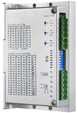
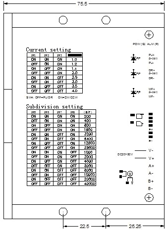
Steps/rev. (1.8°
Motor)
SW5
SW6
SW7
SW8
200
on
on
on
on
400
off
On
on
on
800
on
off
on
on
1600
off
off
on
on
3200
on
on
off
on
6400
off
on
off
on
12800
on
off
off
on
25600
off
off
off
on
1000
on
on
on
off
2000
off
on
on
off
4000
on
off
on
off
5000
off
off
on
off
8000
on
on
off
off
10000
off
on
off
off
20000
on
off
off
off
40000
off
off
off
off
Please shut down and re-apply power after micro-step setting is changed!
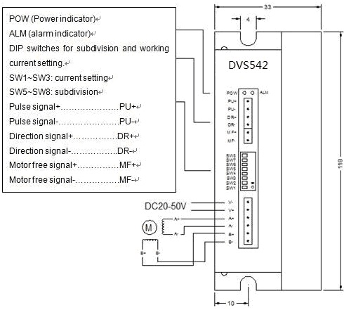
ALM (alarm, red light)
Over Current: light on continuing
Over Voltage: light fast blink
Over Heat: light slow blink
Symbol
Description
PU+
Pulse Signal
Positive, from 5V to 28V,
External
resistance is not required when voltage is over 5V.
PU-
Pulse Signal Negative, Active-low, Resistance 220Ω.
Low level 0~0.5V, High level 4~5V, pulse width>2.5μs.
DR+
Direction Signal
Positive, from 5V to 28V,
External
resistance is not required when voltage is over 5V.
DR-
Direction Signal
Negative, Resistance 220Ω.
Low level 0~0.5V, High level 4~5V, pulse width>2.5μs.
MF+
Motor Free Positive,
from 5V to 28V,
External
resistance is not required when voltage is over 5V.
MF-
Motor Free
Negative, Active-low to make the motor free.
V-
Power Ground
V+
Power Supply, DC20~50V
A+
Motor Phase A
A-
B+
Motor Phase B
B-
Peak
Current (A)
SW1
SW2
SW3
1.0
on
on
on
1.2
off
on
on
1.5
on
off
on
2.0
off
off
on
2.5
on
on
off
3.0
off
on
off
3.5
on
off
off
4.0
off
off
off
SW4 defines the standstill current.
off= half
on=full
More Products