DVS2405
Update: 2017/7/14 View:
- Brand: DVS
- Type: DVS2405

Introduction
Tj=25℃
|
Parameters |
Min. |
Typical |
Max. |
Unit |
|
Output Current |
0 |
- |
4.0 |
A |
|
Power Supply |
24 |
- |
50 |
VDC |
|
Response Frequency |
0 |
- |
200 |
KHz |
|
Logic Signal Current |
7 |
10 |
20 |
mA |
|
Isolation Resistance |
500 |
- |
- |
MΩ |
|
Approx Net Weight |
- |
0.48 |
- |
Kg |
Condition
Caution
Avoid dust and corrosive gas/oil
Temp.
0℃ ~ +50℃
Humidity
Under 90% RH
Vibration
5.9m/s2 Max
Storage Temperature
-20℃ ~ +80℃
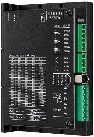
Steps/rev. (1.8°
Motor)
SW1
SW2
SW3
SW4
400
on
on
on
on
800
off
on
on
on
1600
on
off
on
on
3200
off
off
on
on
6400
on
on
off
on
12800
off
on
off
on
25600
on
off
off
on
51200
off
off
off
on
1000
on
on
on
off
2000
off
on
on
off
4000
on
off
on
off
5000
off
off
on
off
8000
on
on
off
off
10000
off
on
off
off
20000
on
off
off
off
40000
off
off
off
off
SW5
off
Motor
running clockwise
on
Motor
running counter-clockwise
SW6
off
Single-ended
control signal, PU=PUL, DR=DIR
on
CW/CCW,
PU=PUL+, DR=PUL-
Please shut down and re-apply power after micro-step setting is changed!
ALM (alarm, red light) flashes 5 seconds circularly.
|
Code |
Time(s) of Flash |
Description |
|
1 |
continuous light-on |
over current |
|
2 |
2 |
over voltage |
|
3 |
3 |
over heat |
|
4 |
4 |
position error |
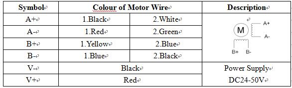
Symbol
Description
5PUL+
Pulse
Signal Positive, from 5V to 28V,
External
resistance is required when voltage is over 5V.
5PUL-
Pulse Signal Negative, Active-low, Resistance 220Ω.
Low level 0~0.5V, High level 4~5V, pulse
width>2.5μs.
5DIR+
Direction
Signal Positive, 5V.
External
resistance is required when voltage is over 5V.
5DIR-
Direction
Signal Negative, Resistance 220Ω.
Low level 0~0.5V, High level 4~5V, pulse
width>2.5μs.
5ENA+
Enable
Signal Positive, 5V.
External
resistance is required when voltage is over 5V.
5ENA-
Enable
Signal Negative, the motor stops.
Symbol
Description
Remark
Pend+
In-position output, Positive
Output signal through the opto-isolated.
Max voltage 30V,
Max current 500mA.
Pend-
In-position output, Negative
ALM+
Alarm output, Positive
ALM-
Alarm output, Negative
Symbol
Description
Motor Wire
1_EB+
B-phase input, Positive
Yellow
2_EB-
B-phase input, Negative
Green
3_EA+
A-phase input, Positive
Black
4_EA-
A-phase input, Negative
Blue
5_+5V
Power supply, 5V+
Red
6_GND
Power supply, ground
White
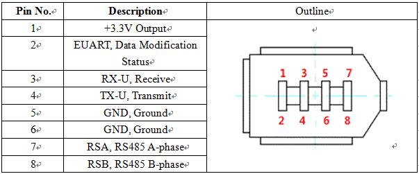
Modbus Register
|
Address |
Function |
Range |
Parameter |
|
00 |
Work Mode |
0-1 |
0: Position Mode 1: Velocity Mode |
|
01 |
Motor Enable |
0-1 |
0: Motor Disabled (Free) 1: Motor Enabled (Engaged) |
|
02 |
CW/CCW |
0-1 |
Invalid |
|
03 |
Subdivision |
400-40000 |
- |
|
04 |
Position-in Signal |
0-1 |
Invalid |
|
05 |
Error Code |
0-3 |
0:Normal 1: Over current Protection 2: Over voltage Protection 3: Over heat Protection |
|
06 |
Engaged Current |
1.0 – 4.0 (A) |
Default: 1 A |
|
07 |
Running Current |
1.0 – 4.0 (A) |
Default: 2 A |
|
08 |
16-bit high position record |
-2147483648 - 2147483647 |
A signed 32-bit data format |
|
09 |
16-bit low position record |
||
|
0A |
- |
- |
- |
|
0B |
- |
- |
- |
|
0C |
- |
- |
- |
|
0D |
- |
- |
- |
|
0E |
- |
- |
- |
|
0F |
- |
- |
- |
|
10 |
Executing Status |
0-1 |
0: Tasks finished 1: Tasks unfinished |
|
11 |
Run/Stop |
0-1 |
0: Stop 1: Run |
|
12 |
Direction |
0-1 |
0: CW-Clock wise 1:CCW-Counter clockwise |
|
13 |
16-bit high displacement |
0 - 4294967295 |
An unsigned 32-bit data format |
|
14 |
16-bit low displacement |
||
|
15 |
Velocity |
0-3000 (rpm) |
- |
|
16 |
Accelerogram |
0-2000ms |
- |
|
17 |
16-bit high absolute position |
-2147483648 - 2147483647 |
A signed 32-bit data format |
|
18 |
16-bit low absolute position |
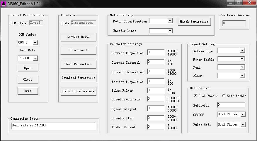
Programming Tool (V1.24)
Name
Value Range
Description
Current Proportion
1000 – 12000
Proportional parameter of
current
Current Integral
1 – 120
Integral parameter of current
Current Saturation
2000 – 26000
Saturation value of current
Position Proportion
1 – 500
Gain value of position
Pulse Filter
1 – 2048
Filtering time range: 0 – 13ms
Speed Proportion
800000 – 3000000
Proportional parameter of velocity
Speed Integral
1000 – 60000
Integral parameter of velocity
Speed Filter
2000 – 20000
Feedback velocity filter
parameter
PosErr Exceed
1 – 40000
Position error exceed
Name
Value Range
Description
Active Edge
Falling / Rising
Related to 5PUL and 5DIR
Motor Enable
High / Low
Active-high / Active-low,
related to 5ENA
Pend
Open / Close
The act after motor reaches
target position
Alarm
Open / Close
The act when alarm occurs
Name
Value Range
Description
Dial Enable
-
Enabled by the hardware DIP
Soft Enable
-
Enabled by the program tool
Below is under the condition of “Soft
Enable”.
Subdivide
400 – 51200
Number of pulse in one motor
revolution
CW/CCW
CW / CCW
The act when alarm occurs
Pulse Moe
PU+DR / CW+CCW
Related to 5PUL and 5DIR
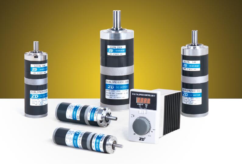
More Products