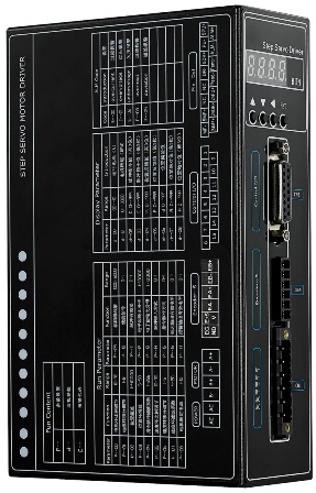
DVS2811D
Update: 2017/7/14 View:
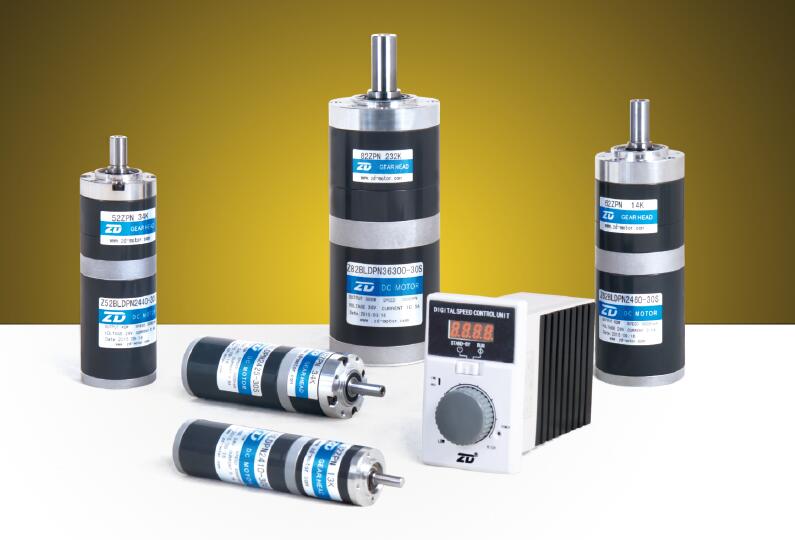
- Brand: DVS
- Type: DVS2811D

Introduction
Tj=25℃
|
Parameters |
Min. |
Typical |
Max. |
Unit |
|
Output Current |
0 |
- |
10 |
A |
|
Power Supply |
40 |
110 |
130 |
VAC |
|
Response Frequency |
0 |
- |
200 |
KHz |
|
Logic Signal Current |
7 |
10 |
20 |
mA |
|
Isolation Resistance |
500 |
- |
- |
MΩ |
|
Approx Net Weight |
- |
1.5 |
- |
Kg |
Condition
Caution
Avoid dust and corrosive gas/oil
Temp.
0℃ ~ +50℃
Humidity
Under 90% RH
Vibration
5.9m/s2 Max
Storage Temperature
-20℃ ~ +80℃
Control Panel
|
Key |
Function |
|
↑ |
UP, Increase Value |
|
↓ |
DOWN, Decrease Value |
|
← |
ESC, Cancel |
|
SET |
Set, Enter, OK |
The longer time pressing on the up or down keys, the faster ratio increased or decreased.
The changed setting will be effective and the error will be cleared after the driver is re-powered.
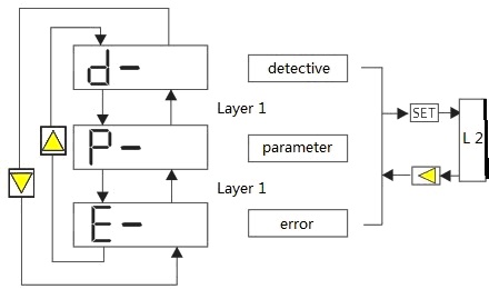
Parameter Setting, P-
The LED will blink twice after setting successfully rewritten.
|
Code |
Displayed Value |
Description |
|
00 |
10--90 |
Current Ratio |
|
01 |
1--8 |
Current Integral |
|
02 |
1--40000 |
Position Deviation |
|
03 |
5--50 |
Position Gain |
|
04 |
1--256 |
Pulse Filter Ratio |
|
05 |
10--30 |
Speed Ratio |
|
06 |
1--5 |
Speed Integral |
|
07 |
4--20 |
Speed Filter Ratio |
|
08 |
1--10 |
Motor Rated Current |
|
09 |
1000--5000 |
Encoder Line Number |
|
10 |
0--1 |
Enable Signal |
|
11 |
0--1 |
Pulse Active Level |
|
12 |
1--10000 |
E-Gear Numerator |
|
13 |
1--10000 |
E-gear denominator |
|
14 |
0--1 |
Pulse Input Mode |
|
15 |
0--1 |
Pulse/Direction |
|
16 |
0--1 |
Finish Work Active Level |
|
17 |
0--1 |
Alarm Active Level |
|
18 |
Software Version |
Reserved |
Micro-step setting
P-12 and P-13 determine the micro-step setting.
P×G=N×C×4
P: micro-step
G: E-gear ratio
N: motor rotates circle number
C: encoder (p/r), DVS2811D’s C=1000
Example
P=10000 for 1 motor circle
G=N×C×4 / P
=1×1000×4 / 10000
=2 / 5
So P-12=2, P-13=5
Detective, d-
|
Detective |
Act |
Sample |
Description |
||||||||||||
|
d--00 |
SET
|
2.5 |
Motor Current 2.5A |
||||||||||||
|
d--01 |
1000 |
Motor Speed 1000r/min |
|||||||||||||
|
d--02 |
C 239 |
Pulse Value 13239 |
|||||||||||||
|
d--03 |
C. 13 |
||||||||||||||
|
d--04 |
P 432 |
Position Feedback Pulse Value 24432 |
|||||||||||||
|
d--05 |
P. 24 |
||||||||||||||
|
d--06 |
10 |
Position Deviation Pulse Value 10 |
|||||||||||||
|
d--07 |
A 722 |
Position Absolute Value 18722 |
|||||||||||||
|
d--08 |
A. 18 |
||||||||||||||
The EEPROM stores up to 10 error codes. LED shows the latest error code. They are all readable by the PC and/or the text display.
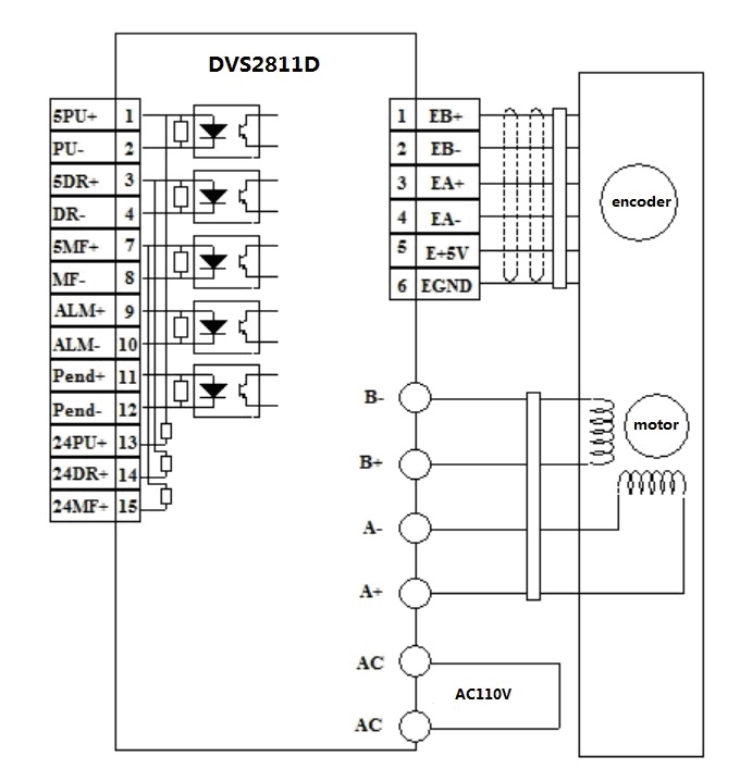
CN1 Connection
Symbol
Colour of Motor Lead
Description
A+
Blue
Close-loop stepper motor wiring
A-
Black
B+
Green
B-
White
AC
Power Supply, AC110V
AC
CN2 Connection
Symbol
Colour of Encoder Lead
Description
EB+
Blue
B-phase
Input +
EB-
Black
B-phase
Input -
EA+
Yellow
A-phase
Input +
EA-
Green
A-phase
Input -
E5V
Red
Power
Supply, 5V+
EGND
White
Power
Supply, Ground
CN3 Connection
Pin No.
Symbol
Description
1
5PUL+
Pulse
Signal Positive, 5V.
External
resistance is required when voltage is over 5V.
2
5PUL-
Pulse Signal Negative, Active-low, Resistance 220Ω.
Low level 0~0.5V, High level 4~5V, pulse
width>2.5μs.
3
5DIR+
Direction
Signal Positive, 5V.
External
resistance is required when voltage is over 5V.
4
5DIR-
Direction
Signal Negative, Resistance 220Ω.
Low level 0~0.5V, High level 4~5V, pulse
width>2.5μs.
5
NC
No
Connect
6
NC
No
Connect
7
5MF+
Enable
Signal Positive, 5~24V.
External
resistance is required when voltage is over 5V.
8
5MF-
Enable
Signal Negative, active-low, the motor stops.
9
ALM+
Alarm
Output Positive, 30V, 500mA
10
ALM-
Alarm
Output Negative, 30V, 500mA
11
Pend+
In-position
Signal Positive, 30V, 500mA
12
Pend-
In-position
Signal Negative, 30V, 500mA
13
24PU+
Opto-isolated
Input Positive, 24V
14
24DIR+
Opto-isolated
Input Positive, 24V
15
24MF+
Opto-isolated
Input Positive, 24V
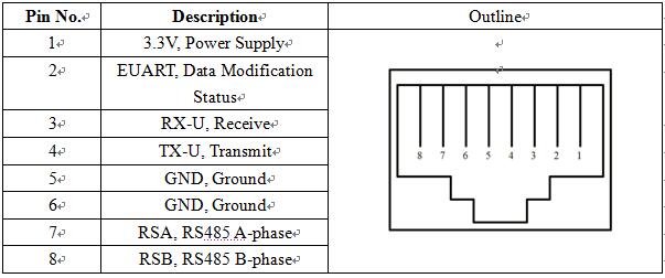
RS232/RS485
The cable between PC’s serial port or STU debugger and the DVS2811D should be the twisted-pair shielded one. Plug-in and unplug should not be conducted while the power is on. The cable length is advised to be less than 2-meter.
Modbus Register
The length of register is 16-bit.
|
Address |
Function |
Range |
Parameter |
|
00 |
Current Ratio |
10-90 |
- |
|
01 |
Current Integral |
1-8 |
- |
|
02 |
Position Deviation |
1-40000 |
- |
|
03 |
Position Gain |
5-50 |
- |
|
04 |
Pulse Filter Ratio |
1-256 |
- |
|
05 |
Speed Ratio |
10-30 |
- |
|
06 |
Speed Integral |
1-5 |
- |
|
07 |
Speed Filter Ratio |
4-20 |
- |
|
08 |
Rated Current |
1-10 |
- |
|
09 |
Encoder (p/r) |
1000-5000 |
- |
|
10 |
Enable Signal |
0-1 |
- |
|
11 |
Active Level |
0-1 |
- |
|
12 |
E-gear Ratio Numerator |
1-10000 |
- |
|
13 |
E-gear Ratio Denominator |
1-10000 |
- |
|
14 |
Pulse Input Mode |
0-1 |
- |
|
15 |
Pulse Direction |
0-1 |
- |
|
16 |
In-position Active Level |
0-1 |
- |
|
17 |
Alarm Active Level |
0-1 |
- |
|
18 |
Firmware Version |
- |
- |
|
19 |
ModBus Slave Add. |
1-255 |
- |
|
20 |
ModBus Baud |
0-9 |
0: 4800 1: 9600 2: 14400 3: 19200 4: 28800 5: 38400 6: 56000 7: 57600 8: 115200 (default) 9: 230400 |
|
21 |
Work Mode |
0-3 |
0:Normal 1: Modbus Relative Position 2: Modbus Absolute Position 3: Modbus Speed |
|
22 |
Status Inquiry |
0-1 |
0: Finished 1: Not Finished |
|
23 |
Rotate Direction |
0-1 |
0: Clockwise 1: Counter-clockwise |
|
24 |
Speed |
0-3000 (rpm) |
|
|
25 |
Acceleration |
0-2000ms |
Trapezoidal’s |
|
26 |
Movement (High) |
0 - 4294967295 |
Unsigned 32-bit |
|
27 |
Movement (Low) |
||
|
28 |
Absolute Position (High) |
-2147483648 - 2147483647 |
Signed 32-bit |
|
29 |
Absolute Position (Low) |
||
|
30 |
Run/Stop |
0-1 |
0: Stop 1: Run |
|
31 |
Position Record (High) |
-2147483648 - 2147483647 |
Signed 32-bit |
|
32 |
Position Record (Low) |
||
|
33 |
Error Code |
0-3 |
0:Normal 1: Over Current 2: Over Voltage 3: Over Heat |
Operation Steps
(1) To set the P-19 slave
address manually
(2) To set the P-20 baud
manually
(3) To write 21 (Work Mode) at
1
(4) To write 23
(5) To write 24
(6) To write 25
(7) To write 26 and 27
(8) To write 30
(9) To read 22, 31 and 32
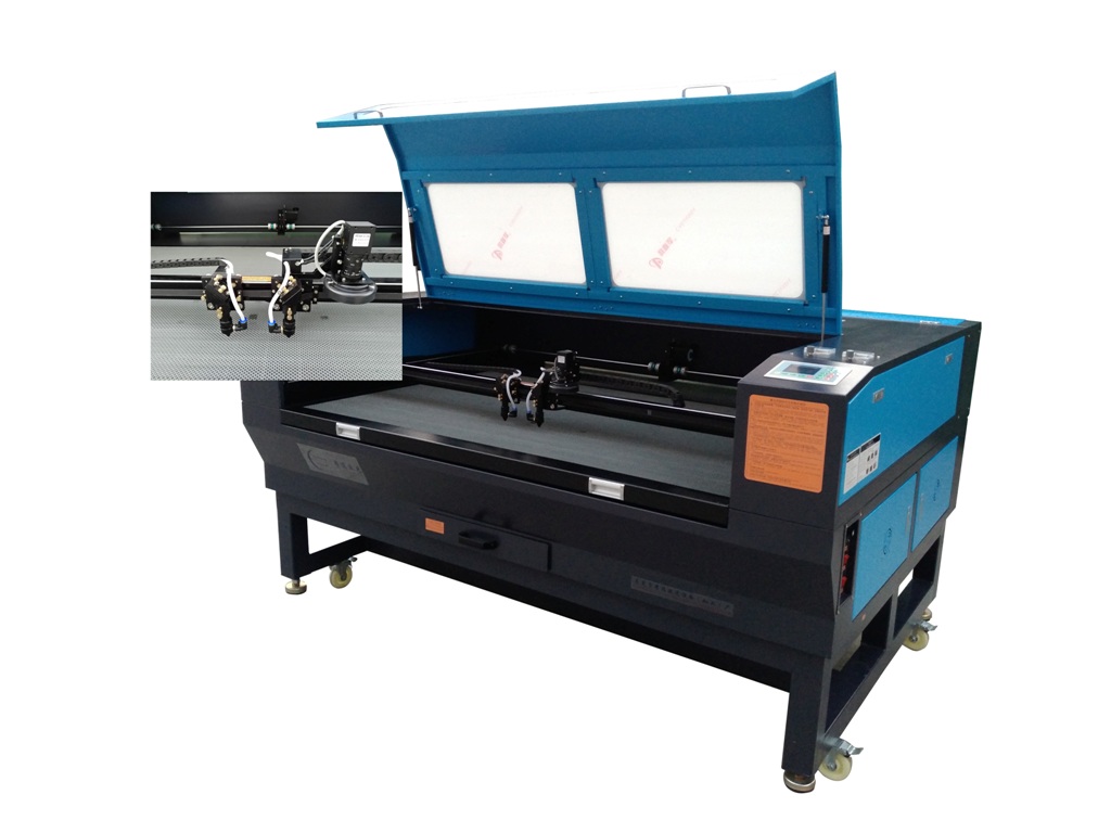
More Products